How to Ground an ESD Mat: Snaps, Cords and Common Ground
How to ground an ESD table mat: snap positions, grounding cords, common ground points and verification, based on published product-page data.

Grounding an ESD table mat takes three parts: a snap fitted to the mat, a cord from the snap to a verified common ground point, and the wrist strap on the same point. This guide covers snap positions, cord connections and the checks that prove the path works.
Why an ungrounded mat does not protect anything
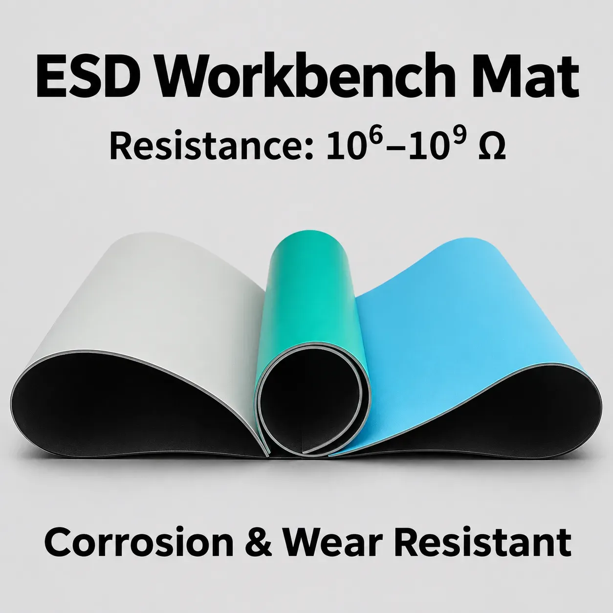
Every ESD table mat on this site is a two-layer construction: a static-dissipative working surface (10⁶–10⁹ Ω on the models that publish a value) over a black conductive backing layer. The surface slows the discharge down; the backing is the layer that carries charge away — the MS-E017 page states it directly: the conductive backing connects to your grounding setup. Without a cord connecting that backing to ground, the charge has nowhere to go and the mat holds static instead of draining it. Grounding is not an accessory step; it is the step that makes the two-layer construction work.
The three parts of a grounded setup
- The mat with a grounding snap. The snap is the electrical contact point through the mat to the conductive backing. On this site, snaps are factory-fitted: MS-E001 lists "grounding snaps can be installed at your required positions", MS-E003 is manufactured with "snaps installed to requirement", and MS-E025 offers "grounding snaps fitted on request — ask for them when you order".
- The grounding cord. The cord connects the snap to the ground point. The product pages list grounding cords among the matching accessories: MS-E001 and MS-E005 both state that matching wrist straps, grounding cords and other grounding accessories are available separately or can be supplied together with the mats, and MS-E003 adds connectors to that list.
- A verified common ground point. The cord terminates at a confirmed ground — an earth bond point, a grounding busbar or the ground terminal of the workstation. "Verified" is the operative word: a point that has never been tested is an assumption, not a ground.
What the product pages publish about grounding
| Model | Grounding provision, as published | Conductive layer resistance | Accessories, as published |
|---|---|---|---|
| MS-E001 | Grounding snaps installed at your required positions | Backing 10³–10⁵ Ω | Wrist straps, grounding cords and other grounding accessories, separately or with the mats |
| MS-E003 | Snaps installed to requirement; snap positions confirmed before the quotation | Backing 10³–10⁵ Ω | Wrist straps, grounding cords and connectors, separately or with the mat |
| MS-E005 | Conductive backing layer for grounding (no snap statement on the page) | Backing 10³–10⁵ Ω | Wrist straps, grounding cords and grounding accessories, separately or with the mat |
| MS-E017 | Conductive backing connects to your grounding setup; listed for grounded workstations | Backing 10³–10⁵ Ω | Not stated on the page |
| MS-E025 | Grounding snaps fitted on request — ask when you order | Conductive layer 10³–10⁶ Ω | Not stated on the page |
Two readings matter. First, snap fitting is an order-time decision on this range, not a field improvisation: the position is agreed before production, which is why the custom-cut ordering flow treats snap positions as part of the specification. Second, the conductive layer values differ by model — MS-E025 publishes 10³–10⁶ Ω where most pages publish 10³–10⁵ Ω — so read the row for the model you are ordering rather than assuming one range covers all 26 models; the 26-model comparison shows which pages publish a value at all.
Step by step: connecting the mat to ground
- Fit or confirm the snap. If the mat was ordered with snaps fitted, confirm the snap is seated through the mat at the agreed position. If you are specifying a new mat, mark the snap position on your drawing or dimension sheet — a corner position on the operator side keeps the cord run short.
- Attach the cord to the snap. Push the cord's connector onto the snap until it is fully seated. A half-seated connector is the most common silent failure: the setup looks complete and conducts nothing.
- Run the cord to the common ground point. Keep the run short, fixed so it cannot be pulled loose, and routed off the walking path. Terminate it at the verified ground point — earth bond, busbar or workstation ground terminal.
- Put the wrist strap on the same point. The operator and the mat must share one discharge path. A wrist strap grounded at a different point than the mat can leave a voltage difference between the person and the work surface, across the board being handled.
- Verify the complete path. Measure the resistance from the mat surface to the ground point with a resistance meter. This tests the whole chain — surface, backing, snap, cord and ground point — as one path, which is the only configuration that matters in use.
Standards, named without borrowed numbers
Worksurface grounding sits inside the ESD control programme framework of ANSI/ESD S20.20, and worksurface resistance is measured by the method of ANSI/ESD STM4.1. This site does not publish test-condition data (electrode, temperature and humidity conditions) for its resistance values, so this guide names the standards as the framework to specify in your own control plan and states no acceptance limits of its own. If your programme requires documented values under stated conditions, raise that in the enquiry — it is a specification to agree with the supplier, not a number to read off a product page.
Three mistakes that quietly break the setup
- The mat is laid out with no cord attached. It collects dust and holds charge; visually it is indistinguishable from a working setup.
- The cord runs to an unverified point. A painted rail, a random screw or an untested terminal may not be ground at all. Test the point itself before trusting the path.
- The wrist strap uses a different ground point than the mat. Two separate paths can sit at different potentials, and the difference appears across the device on the mat.
Grounding also interacts with the choices made earlier in the buying sequence: mat thickness does not change any of these steps (see the ESD mat thickness guide), but a roll that will be cut into several benches needs a snap plan per bench, not per roll.
Ordering a grounded setup
Send the bench dimensions or drawing, the quantity, the application and the delivery country, and mark where each snap should sit. The MS-E003 quotation flow confirms feasibility, cutting details and grounding snap positions before pricing, and the accessory pages offer cords and wrist straps supplied together with the mats, so the first setup arrives as one kit. Order quantities across the range suit sample evaluation, trial sales and workstation projects, so a single grounded bench can be evaluated before a wider rollout.
Frequently Asked Questions
Where should the grounding snap be placed on an ESD mat?
The product pages do not prescribe one position; they offer snaps installed at the positions you require (MS-E001) or to requirement (MS-E003). In practice, mark the position on your drawing before production — an operator-side corner keeps the cord run short and off the walking path. The position is confirmed with the quotation.
Does every model on this site come with a grounding snap?
No default is published. MS-E001, MS-E003 and MS-E025 state that snaps are installed on request or to requirement; other pages, such as MS-E005 and MS-E017, describe the conductive backing and grounding accessories without a snap statement. If your setup needs a snap, name it in the enquiry so it is fitted before dispatch.
What resistance should I measure from the mat surface to ground?
This site publishes the layer values — working surface 10⁶–10⁹ Ω and conductive backing 10³–10⁵ Ω on most models, 10³–10⁶ Ω on MS-E025 — but no surface-to-ground acceptance value or test conditions. Measure the full path with a resistance meter; set your acceptance limit under your own ESD control programme (ANSI/ESD S20.20 framework, STM4.1 method) or agree it with the supplier.
Can the wrist strap and the mat use different ground points?
They should not. The mat and the operator need one shared discharge path at a common ground point. Separate points can sit at different potentials, and that difference can appear across the device being handled. Connect both to the same verified point, then verify the mat's path by measurement.
Are grounding cords and wrist straps included with the mats?
They are published as matching accessories, not as automatic inclusions. MS-E001 and MS-E005 state that wrist straps, grounding cords and other grounding accessories are available separately or can be supplied together with the mats; MS-E003 lists connectors as well. Ask for them on the same order if you want the setup to arrive complete.
Does mat thickness change how grounding is done?
No. The grounding chain — snap, cord, common ground point, verification — is the same for 2 mm, 3 mm and thicker mats, because it depends on the two-layer construction, not the thickness. What changes with thickness is durability and use case, covered in the thickness guide linked above.